


METHODS OF DOCUMENTATION AND MEASURED DRAWINGS
[ARC 1215]
Our Main Objective
was to experience first handedly on how an actual measured drawing, an architectural representation drawn to the scale of an existing building of an existing strucure is executed.
As an assignment for this practicum semester, our task was to obtain information and measured data straight from site and produce them in drawings, portraying the current condition of the building. As a result, we are to provide some form of documentation and record as reference for future use, such as the building's structural repairs and restoration work.
From this project, we have learnt to demonstrate an understanding of building components, structures and systems in relation to the design of the building, and hence, acknowledged the importance of this task in conserving local achitecture
The Measuring Process
During this stage, our group of 16 carried out a site visit for 5 days to kick start our measuring process. We were separated into subgroups where some of us were assigned on collecting measured data required to produce floor plans, elevations, and sections; and others were assigned in taking photos of the area for visual references, and carry out an interview in preparations for the report.
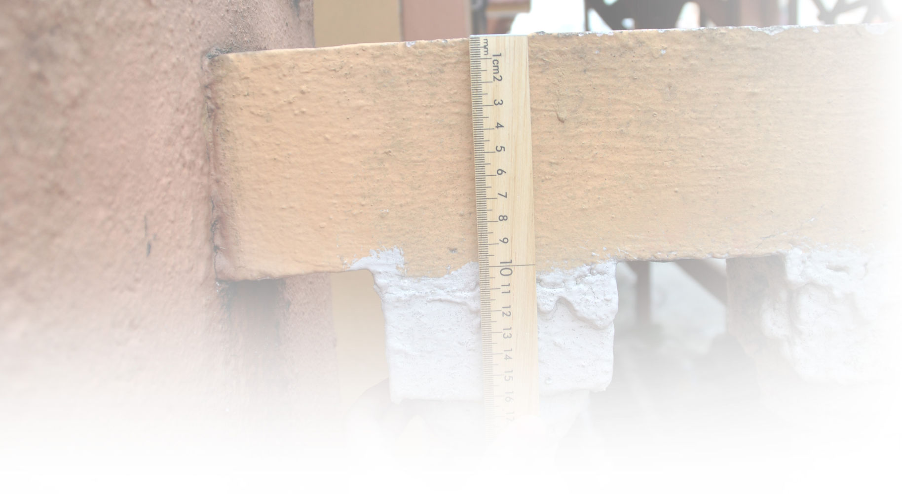
The tools for measuring were measuring tapes, metre rule, and a couple of laser rangefinders. The laser rangefinder aids us as it was able to distance of areas which were unreachable with measuring tape alone. For areas such as the roof length which were unachievable by all the tools we possessed, that measuring was made possible with the aid of the staffs in the fire station as they have the tools and equipment that enables access to those areas, for example, the station's long ladder.
Throughout the measuring process, we made sure that we obtain measured data from every single part of the building down to very small details so that we won't miss out any important data.
Aside from that, our group's report team has carried out an interview to one of the staff members as to gain further understanding regarding the history of the fire station.


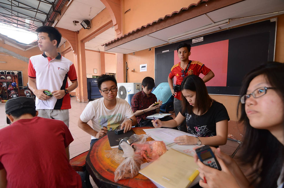


An interview with a staff member regarding the history of the fire station.

Documentation
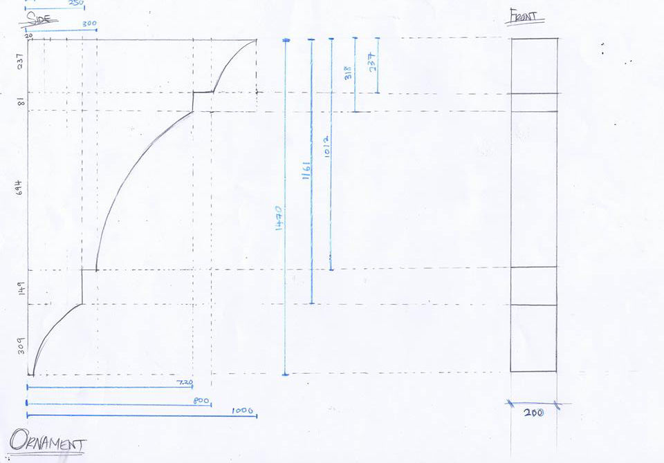
After all measured data were collected at the site, the rough data were transferred to CAD Drawing. The initial drawing to be produced was the floor plan, as the main data that hold as a reference to all other drawing. Other main drawing was produced later on, those were the elevation, cross section, ornaments and construction details, roof, and other elements that we found in the building. The workload was separated equally between groups respectively in different section of the required drawing.
As each members measured with different equipments and methods of measuring, there is bound to be human error and inconsistent accuracy. Thus once the main drawings are complete, the drawings were compared along with adjustment between groups to make sure all drawings are well aligned to each other. Although unimportant, small details such as standardize doors and windows which were added after the renovation were not ignored for the purpose of model making, along with the axonometric drawing projection of all the details.
After the drawings were finalized and approved, they were placed in the same layouts along with adjusted lineweight for consistency and ready to be printed hence completing the documentation process. Samples of the AutoCAD drawings can be viewed in the gallery page here.
The measuring process was repeated several times between group comparisons to ensure accuracy in all drawings.


From top left across: The standardized door and windows that were to be included in drawings.
From far left across: Samples of measurements on sketches where were to be transfered into AutoCAD drawings.

Model Making
Once all the drawings were finalized, they were scaled down and printed out as reference for making the model of the building in an appropriate size where it'll stand on an A2 wooden board. The scale chosen was 1:75 and the material used to build the model was balsa wood.
Most parts of the model were mede by hand except certain parts such as the roof tiles and balustrades as they were unable to be produced manually. Hence, they were made by laser cutting to ensure consistency in thicknesss and size. As the interior structure was the main focus of the model, the roof were installed in such a way that it can be detached from the walls, the trusses, on the other hand, were simplified and their numbers reduced in order to provide a clearer view to the interior.
When the model's complete, it was placed and attached to an A2 board containing the site name and names of all group members.
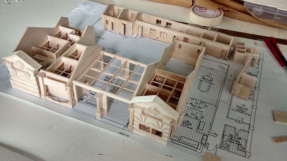
The model before adding the roof system.

The installation of trusses in progress.

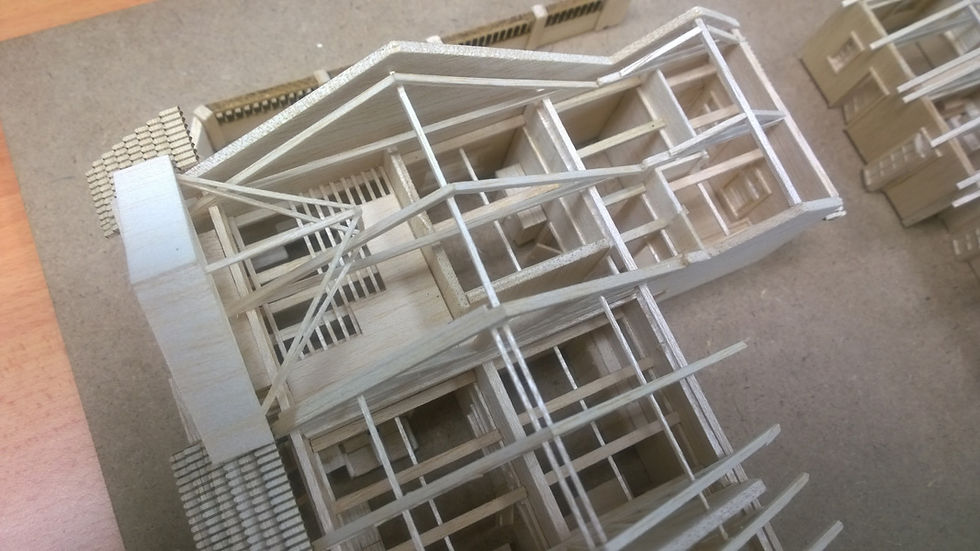
The truss system was simplified to have a clearer view of the interior of the structure .

Certain details that cannot be produced manually was then made by laser cutting.

The complete and finished model ready for submission. The name were laser-cut into the wooden board along with names of the group members.

The roof tiles created by laser cutting.

The balustrade done by laser cutting.

The complete model with the roof detached.
The laser cutting process of the roof tiles.